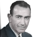
James Franck: After winning the Nobel prize in 1926, the career of James Franck took several sharp turns as the world drifted toward war. Shortly after Hitler's rise to power, Franck resigned as a professor of physics at the University of Göttingen to protest the Nazis' newly passed anti-Semitic legislation. An academic refugee, he taught at Johns Hopkins and Copenhagen before making his way to The University of Chicago, where he remained on the faculty until his death in 1964.
Credit: The University of Chicago Library
After I graduated I hunted for a job in commercial art, without success. I applied to graduate school at Johns Hopkins and also at Caltech, because my buddy was planning to go there. Well, my family decided where I should go. In 1936 it cost about $2.50 to go to Baltimore from New York, but it cost $40 to go to California. My mother felt if I ever got that far away, I'd never come back, so she insisted I go to Hopkins.
I vividly remember my first day in the physics department at Hopkins. The secretary took me down to see Professor James Franck. I hardly knew who he was at that time. He was a Nobel Prize winner and a truly great man. And he had a very fatherly look about him, sort of a portly, handsome man. He smoked a big cigar, and ashes kept falling on his vest, but he was totally indifferent to it. He was very relaxed, and talked to me for about two hours. He tried to understand what my aptitudes might be, and to prescribe courses, and sort of generally indicate the direction I might take. I appreciated only later on what it meant to have two hours of James Franck's time and that kind of discussion as a new student.
I decided to do my thesis work with Franck and he was willing to take me on. Then, just when I was getting organized to start my research, he moved to the University of Chicago. But I went ahead with my research, developing a Geiger counter that improved the sensitivity of an ionization chamber used to detect X-ray particles. Within a month I had enough data to write my thesis. Then I wrote several other papers studying X-ray interactions with materials using this instrument.
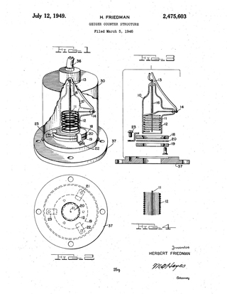
Herbert Friedman's Geiger Counter: Friedman holds U.S. Patent No. 2,475,603, for an adaptation of the tube used in a Geiger-Mueller counter. His tube design increased the counter's sensitivity to weak radiation sources by lowering the background noise of the counter itself. Figure 1 (upper left) is a cut-away view of Friedman's counter tube mounted within a container, called a shield. Figure 2 (lower left) is a front-end view of the tube. Figure 3 (upper right) is a cross-section of the tube showing the arrangement of parts and the structure used for mounting the tube within the shield. Figure 4 (lower right) is a cross-section diagram showing the tube anode and cathode, and a plot of the electric field within the tube.
Credit: Public Domain


